A typical series resonant circuit is shown in the figure below.

The total impedance:
In many cases, R represents the loss resistance of the inductor, which in the case of air core coils simply means the resistance of the winding. The resistances associated with the capacitor are often negligible.
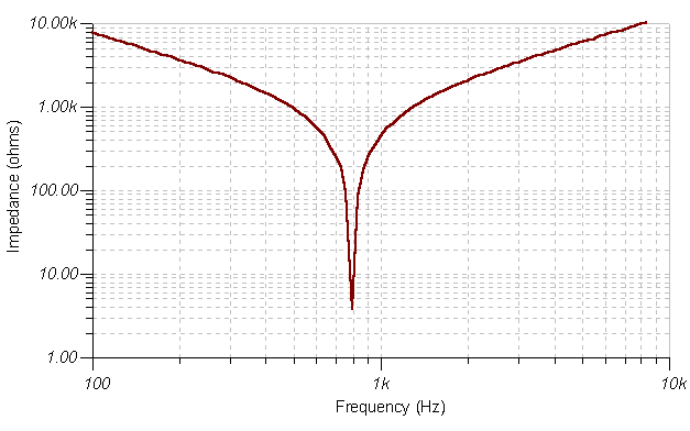
The impedances of the capacitor and inductor are imaginary and have opposite sign. At the frequency w0L = 1/w0C, the total imaginary part is zero and therefore the total impedance is R, having a minimum at the w0 frequency. This frequency is called the series resonant frequency.
The typical impedance characteristic of the circuit is shown in the figure below.

From the w0L = 1/w0C equation, the angular frequency of the series resonance:
![]()
or for the frequency in Hz:
f0 = ![]()
This is the so-called Thomson formula.
If R is small compared to the XL, XC reactance around the resonant frequency, the impedance changes sharply at the series resonant frequency In this case we say that the circuit has good selectivity.
The selectivity can be measured by the quality factor Q
![]()
If the angular frequency in the formula equals the angular frequency of resonance, we get the resonant quality factor:
![]()
There is a more general definition of the quality factor:
![]()
The voltage across the inductor or capacitor can be much higher then the voltage of the total circuit. At the resonant frequency the total impedance of the circuit is:
Z=R
Assuming that the current through the circuit is I, total voltage on the circuit is
Vtot=I*R
However the voltage on the inductor and the capacitor
![]()
Therefore
![]()
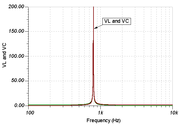
This means at the resonant frequency the voltages on the inductor and the capacitor are Q0 times greater than the total voltage of the resonant circuit.
The typical run of the VL, VC voltages is shown in the figure below.

No comments:
Post a Comment